The Ultimate TransmatchA lifelong friend of mine was fond of saying, “I was first licensed [in the Amateur Radio service] in 1939. We had never heard of standing wave ratios or impedance matching. We hung our antennas, and if they worked, we used them.” There is nothing wrong with that philosophy. In those days our transmitters were equipped with vacuum tubes, which were relatively forgiving. Nowadays with solid-state RF amplifiers in many of our contemporary rigs, good engineering practices and efficiency dictate we consider SWR and impedances in particular when it comes to maximum power transfer from the transmitter to the antenna, and minimum reflection from the antenna back to the transmitter. Here are examples of how these goals can be accomplished, using either a military surplus L-C tuner or a commercially manufactured unit, along with an antenna analyzer that measures system performance, including load resistance and impedance, the standing wave ratio, and the net reactance at a particular frequency. |
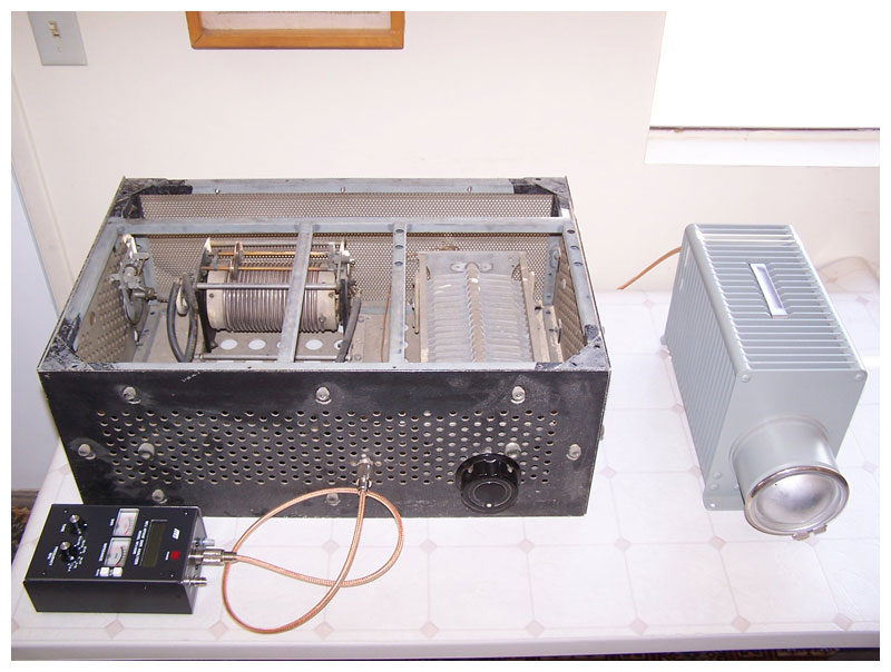
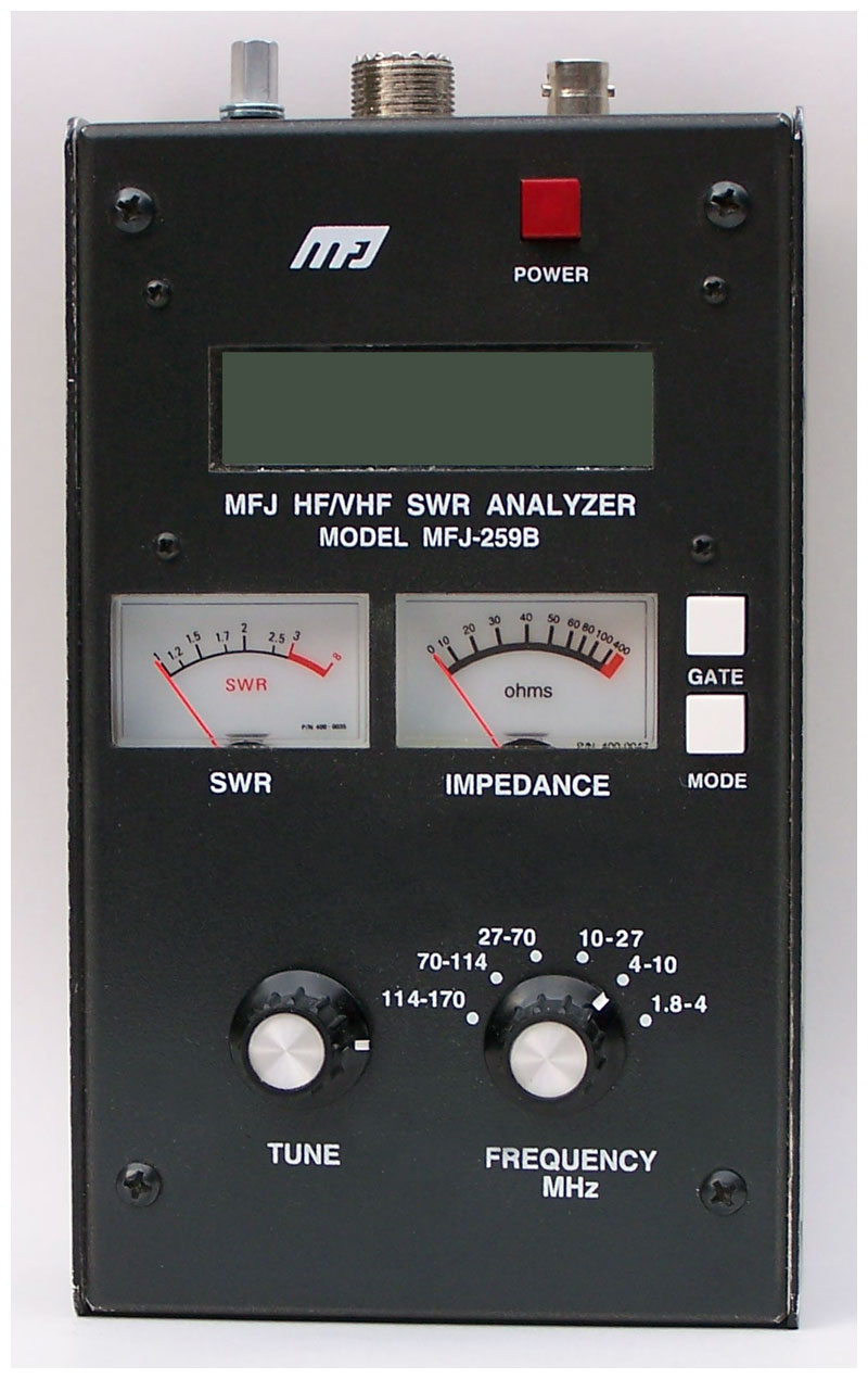
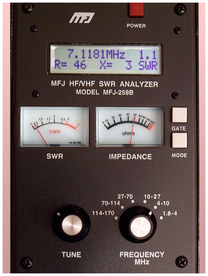
A Bird Termaline dummy load, an MFJ-259B SWR Analyzer,
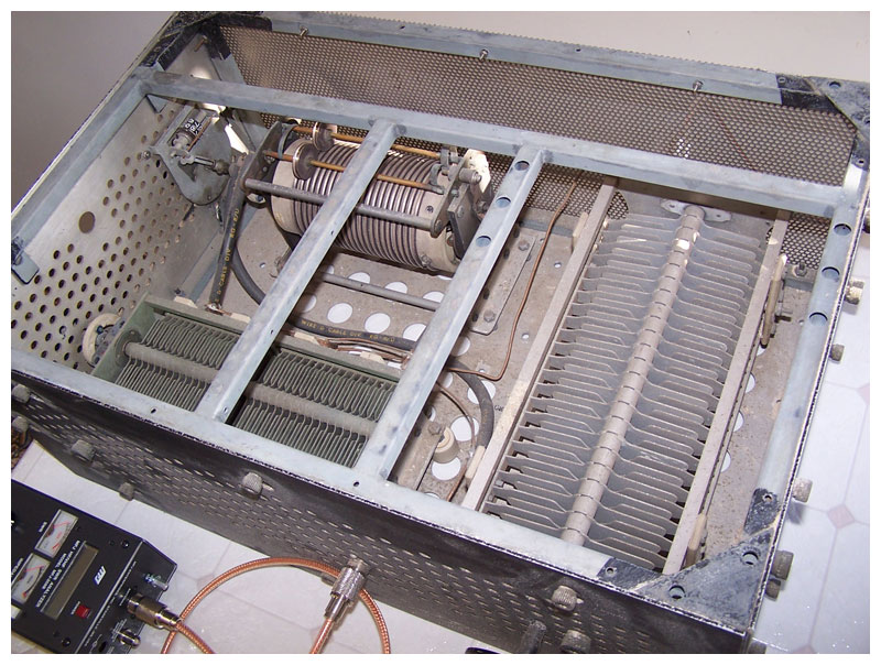
and an L-C tuner built from U.S. Army Signal Corps parts.
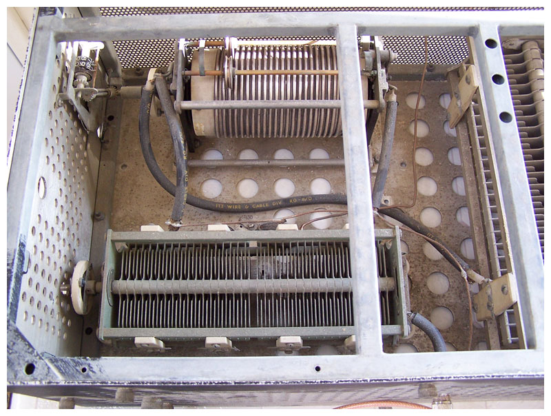
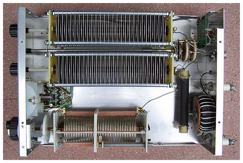
Roller inductor, split-stator input capacitor.
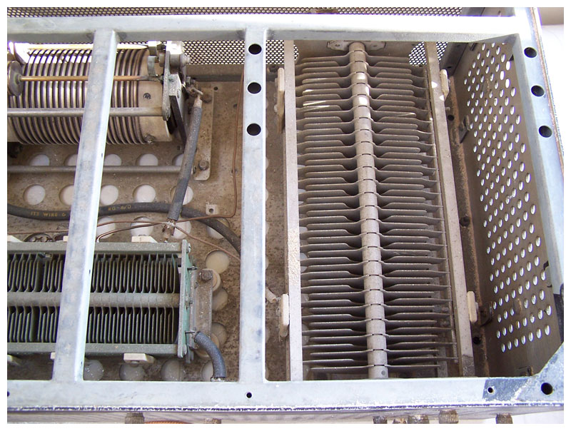
Output capacitor is on the right.
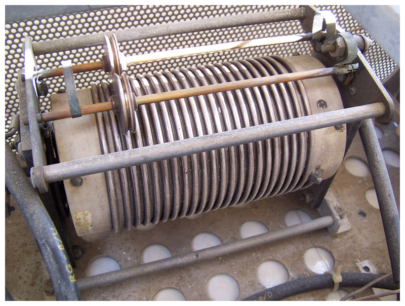
The roller coil.
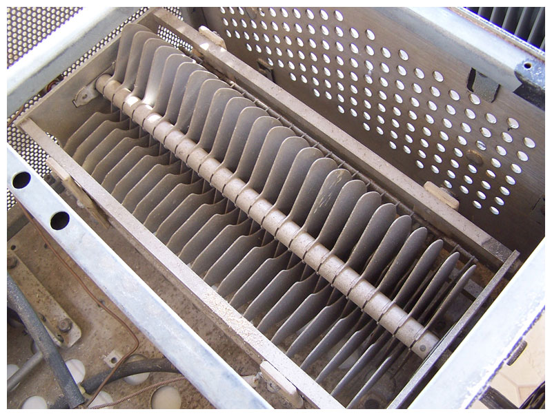
The output capacitor.
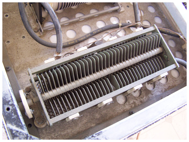
The split-stator input capacitor.
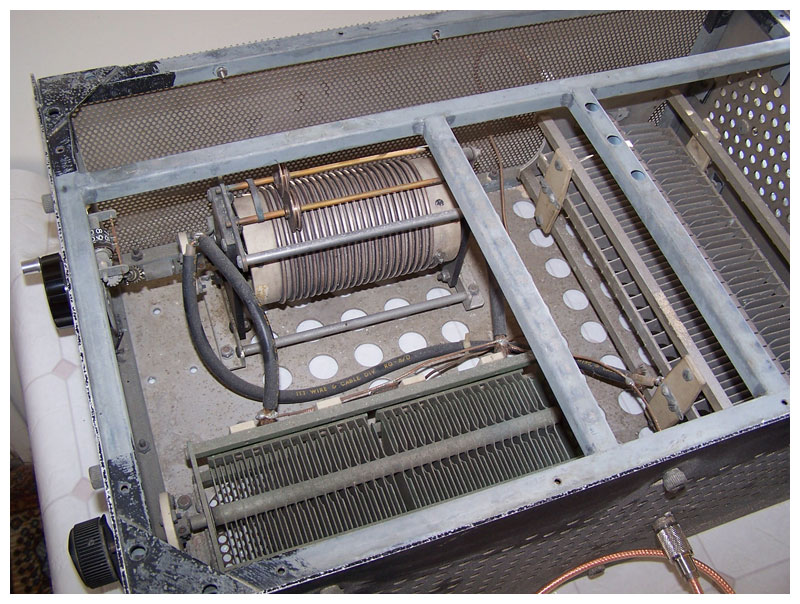
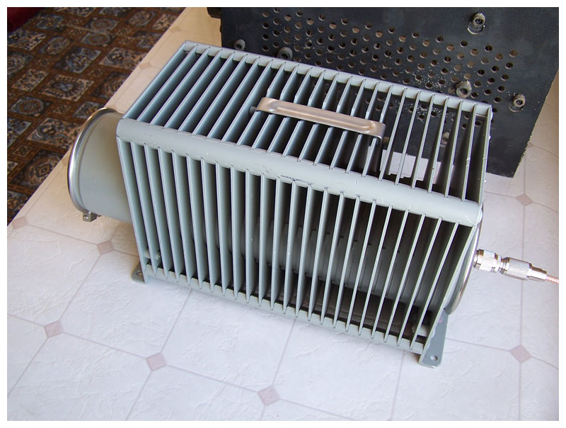
These tuners were used by the military during the Second World War.
This unit is probably capable of power levels up to 5,000 watts.
Schematic diagram of “The Ultimate Transmatch,” designed by Lew McCoy, W1ICP.
|
|
The Bird Termaline.
The MFJ-989C Versa Tuner V
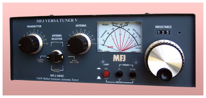
A contemporary antenna tuner with internal instrumentation.
Its components are similar to those of the Signal Corps tuner seen above.
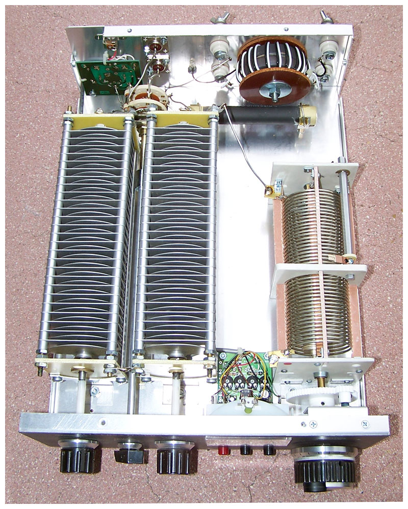
This unit is rated at 3,000 watts.
Here is a slightly larger view of the MFJ-989C schematic.
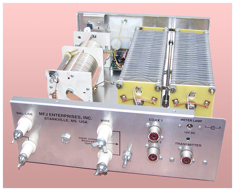
A variety of antennæ can be connected simultaneously, and switch-selected from the front panel.
|