The RCA Type 77-DX poly-directional ribbon microphone
The umber gray television version.
New logo on the last of the 77 series.
Description The RCA Type 77-DX Poly-directional Microphones MI-4045-F and MI-11006-C are high-fidelity microphones of the ribbon type which may easily be adjusted to obtain a variety of directional patterns. Since the MI-4045-F microphone is primarily intended for broadcast use, it is finished in satin chrome and a low-gloss umber-gray enamel. The MI-11006-C microphone is intended for television use and is therefore completely finished in a low-gloss umber-gray enamel which eliminates glaring reflections usually seen on highly polished microphones.
Instead of being open on both sides as in the conventional velocity microphone, the ribbon element in this mic is coupled to an acoustic labyrinth which forms the body portion of the microphone. The tube connecting the back of the ribbon to the labyrinth is slotted directly behind the ribbon and fitted with an adjustable shutter to secure various areas of opening. When the opening is completely closed, the mic operates as a non-directional pressure mic; at the wide-open position the microphone becomes bi-directional. With the proper size opening the pattern becomes a cardioid by virtue of the phase shift which occurs. Openings smaller or larger than this critical size produce directional patterns with various sized rear lobes. Different amounts of low-frequency attenuation are obtained by a reactor shunting the output. These microphones are intended primarily for indoor use and if used outdoors may require some additional protection against the wind.
Directional Characteristics The adjustable shutter over the slot in the tube leading to the acoustic labyrinth may be rotated via a screwdriver adjustment extending through the rear screen flush with a designation plate. The choice of directional patterns makes possible a considerable degree of control of the ratio of direct sound to reverberant sound as well as the possible reduction of unwanted sound such as audience noise in a studio. The wide angle of pick-up provided by the cardioid pattern is useful in covering large groups with a single microphone. For close-talking applications the non-directional characteristic is of considerable value since the low-frequency response is not accentuated as in the case of a velocity microphone. Numerous other applications of the various directional patterns as well as the different response curves will no doubt suggest themselves to the user.
Directional Pattern Selector The plate is marked U, N and B, as symbols for the uni-directional, non-directional and bi-directional patterns. Three additional markings L-1, L-2 and L-3 are used as reference points for other directional patterns which may be obtained. Refer to Figure 4 for the patterns associated with each of the six symbols. Stops are provided on the continuously variable pattern selector at the six marked positions, although the shutter may be set at any intermediate position.
Differences in the 77-D and 77-DX pattern selector escutcheon plates.
The directional pattern selector shutter.
Frequency Response Settings At the bottom of the lower shell, a screwdriver-operated selector is marked M (music), V1 and V2 (voice). The voice positions connect a reactor across the entire secondary or part of the secondary of the output transformer, depending on the switch position. Refer to Figure 5 for the frequency-response characteristics of each setting. As can be seen from the curves, the reactor attenuates the low-frequency response. This is especially desirable when the microphone is less than three feet from the source of sound and the low-frequency response would otherwise be exaggerated.
Quoted from the Radio Corporation of America Industrial Electronic Products Broadcast Audio Equipment Instructions for the Type 77-DX Poly-directional microphone, MI-4045-F and MI-11006-C, circa 1955.
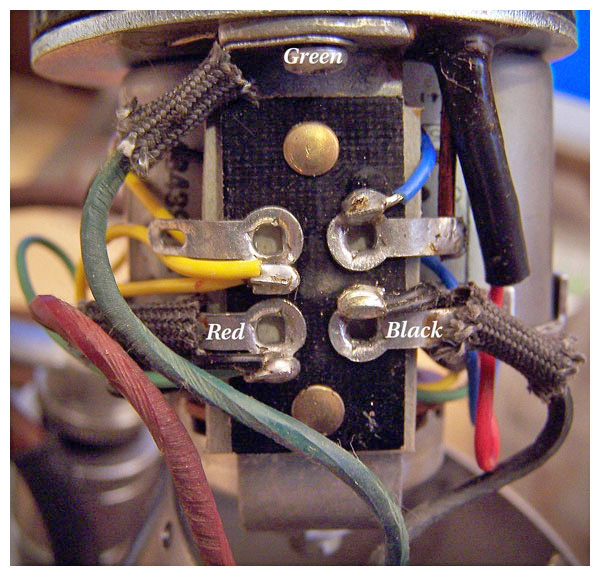
Figure 2 (seen below) found on Page 3 of the 77-DX Instruction Book (available above) are confusing because the smaller postage-stamp-sized Cable Connections drawings are upside-down when compared to the larger part of the diagram. For a 250-ohm connection, follow the large part of Figure 2: Connect the microphone cable’s green lead to the grounding terminal closest to the grille, the red lead to the lower left-hand terminal on the transformer terminal board, and the black lead to the lower right-hand terminal. At the XLR end of the cable, green connects to Pin 1, red to Pin 2, and black to Pin 3.
Height comparison of the 77-C and the 77-DX.
“Reveille with Beverly” Click photo to learn more about Ms. Hay.
Hoagy Carmichael
Norman Corwin narrating One World Flight series, 1947.
“Just because the microphone in front of you amplifies your voice around the world is no reason to think we have any more wisdom than we had when our voices could reach only from one end of the bar to the other.”