The RCA Type 77-C
All-Purpose Microphone
MI-4042-A and MI-4042-B
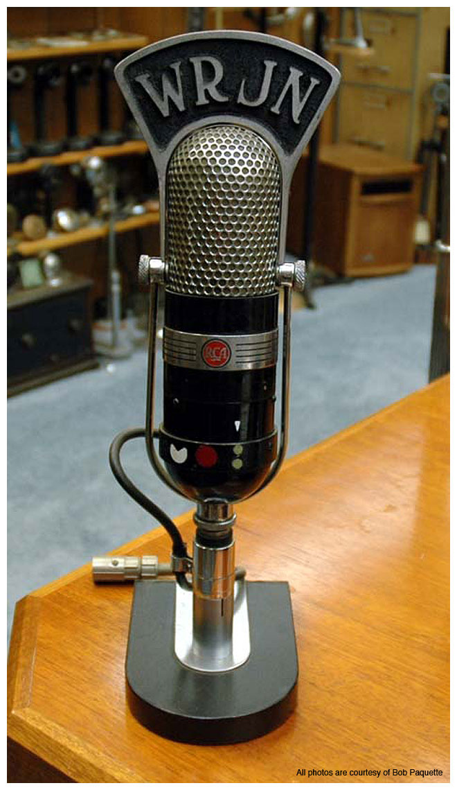
Description
The All-Purpose Microphone consists of two ribbon type microphones operating in a common air gap. One of the units is responsive to the pressure gradient of the sound wave and is commonly called a velocity microphone. The other unit responds to the pressure in the sound wave. The outputs of the two microphones are connected in series and the resultant vector addition of the generated voltages produces a directional characteristic as shown in Figure 1 (c). Characteristics of the velocity and pressure sections are shown at (a) and (b) respectively. The velocity section follows the conventional construction for this type of microphone. The pressure operated section is open on one side and terminated on the other in a folded tube packed with sound absorbing material. This arrangement produces a pressure operated mic which is essentially resistance controlled over the response range. This feature is essential since both the phase and magnitude of the output voltages of both sections must maintain a correct relation over the entire operating range.
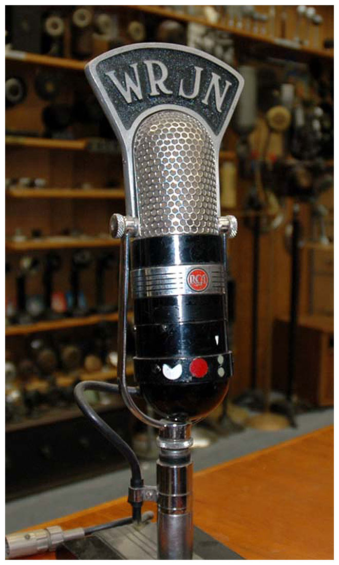
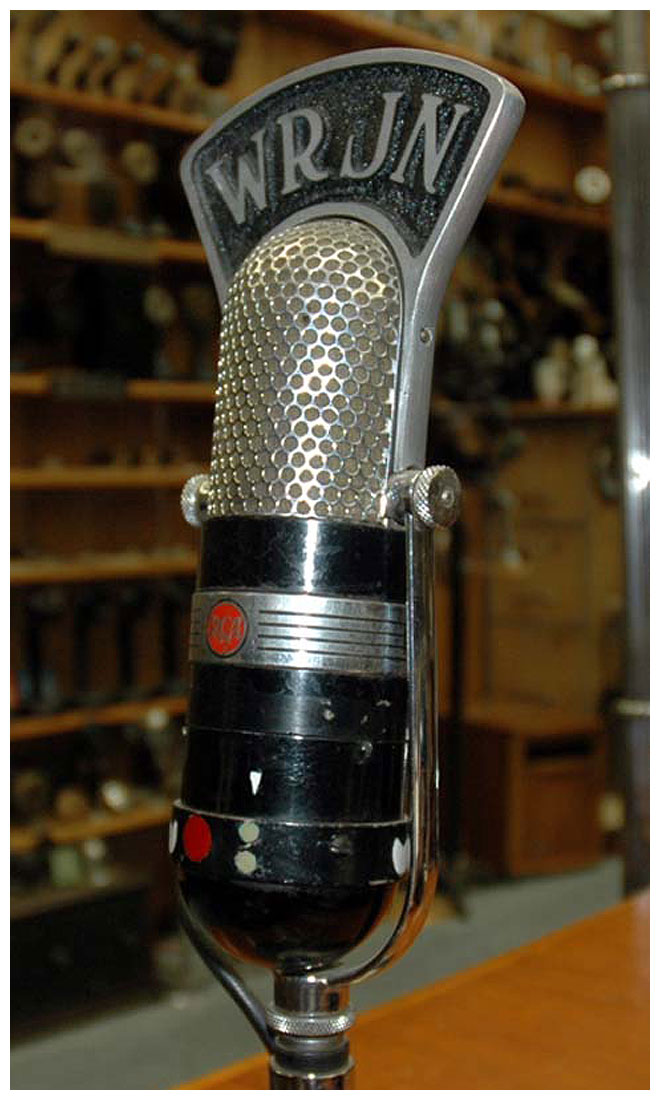
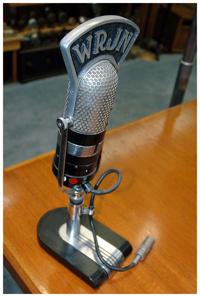
The ribbon and magnet assembly is enclosed in the perforated housing located at the top of the unit. The screen serves to provide wind screening and protection from dust and mechanical injury. The folded tube associated with the pressure section is contained in the cylindrical body. The impedance matching transformer is located in the hemispherical shell at the bottom of the microphone. The microphone may also be operated as either a non-directional or a bi-directional microphone by using the elements comprising the uni-directional microphone separately. An externally operated switching means is provided for this purpose. The cushion mounting is threaded to fit any of the mic stands having a ½-inch pipe thread. Removal of the cushion mounting will allow the microphone to be used with stands having a ⅛-inch pipe thread.
Sensitivity
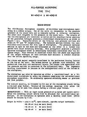
With an input sound pressure of 10 dynes per square centimeter the following output levels will be obtained for uni-directional operation. If the mic is operated into a matched load these levels should be reduced by 6 dB.
Output in volts = 1070 × 10-6, open circuit,
250-ohm output terminals.
Output in volts = −64 dB at 12.5 mW zero level
Output in volts = −61 dB at 6 mW zero level
Output in volts = −54 dB at 1 mW zero level
Non-directional and bi-directional opera-
tion will result in a 3-dB loss in output.
Response Characteristics
The operating range of the microphone extends from 40 to 10,000 cycles when used as either a uni-directional or bi-directional microphone and from 60 to 10,000 cycles when used as a non-directional mic. The output of both the bi-directional and uni-directional microphones will show increased low frequency response when the microphone is located less than two feet from a source of sound. The effect is, however, much less pronounced for uni-directional operational than bi-directional operation. This effect is absent when the non-directional connection is used.
DIRECTIONAL CHARACTERISTICS
Uni-Directional Operation
On the front or operating side of the microphone the response is uniform, while at the rear of the microphone sounds are attenuated by an average of 14 to 20 dB, thus giving approximately a 10-to-1 ratio of desired to undesired pick-up. Sound waves originating in front and along an axis perpendicular to the plane of the ribbon will, naturally, have the maximum effect. The actual measured response of the uni-directional microphone, as shown in Figure 2, approaches a cardioid very closely. For all frequencies up to 4000 cycles the cancellation is very good. At higher frequencies a small “tail” occurs because of the slight phase displacement that begins to become noticeable in this range.
Bi-Directional Operation
The directional pattern is shown to approximation in Figure 1 (a). This characteristic remains substantially unchanged with frequency.
Non-Directional Operation
The response is essentially non-directional from 60 to 10,000 cycles over an angle of 180 degrees, and from 60 to 5000 cycles over 360 degrees. For the same allowable reverberation pick-up, the operating distance of the bi-directional and uni-directional mic is approximately 1.73 times greater than that of a non-directional microphone.
Cable Connections
the MI-4042-A Microphone has an output impedance of 250 ohms, and MI-4042-B an impedance of 50 ohms. It is not possible to convert from one impedance to the other except by a complete change of transformer.
Operation
The microphone may be used either as:
1. Uni-directional microphone
2. Bi-directional (velocity) microphone
3. Non-directional (pressure) microphone
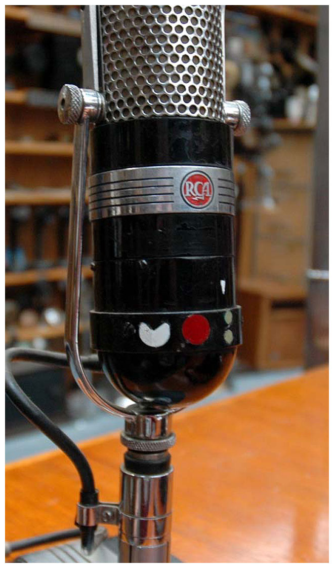
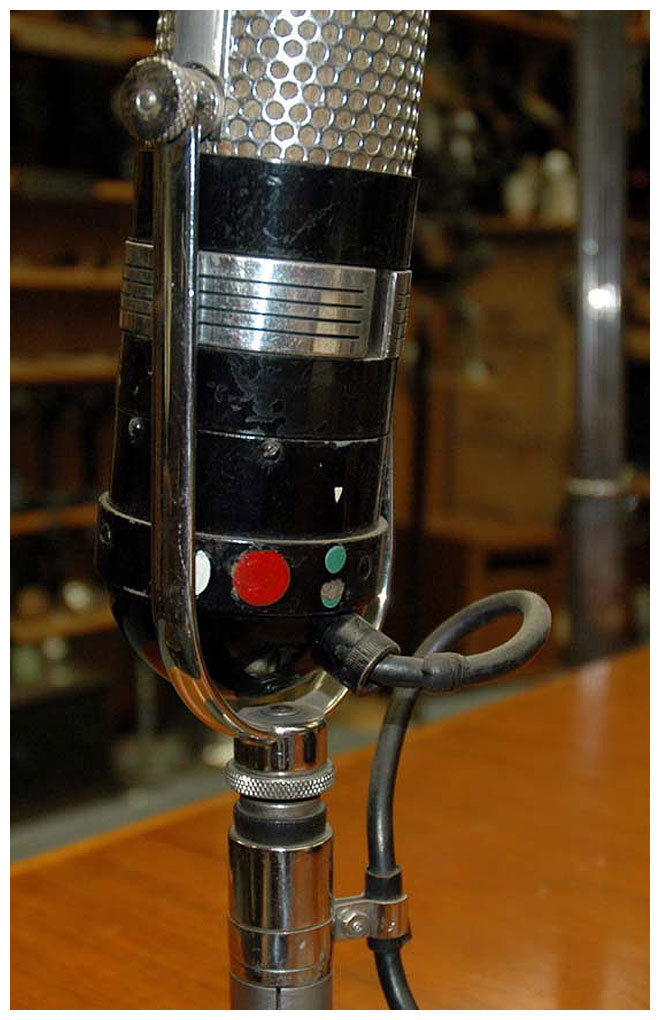
The change is effected by rotating the ring located at the top of the hemispherical base until the picture of the directional pattern desired lines up with the index mark on the case. These patterns, in color, are placed on both the front and back of the unit and may be identified by referring to Figure 1 (a), (b) and (c).


A historical note—RCA microphone restoration expert Jerry Silvia says: “The C is the rarest of the chrome/black series as they were destroyed by the repair center when they were returned for repair and replaced with the C1 at no charge. They were a failed attempt to offer an external directional pattern selector switch.
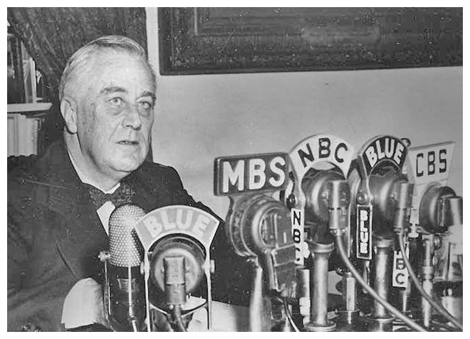
President F. D. Roosevelt delivers a Fireside Chat on January 11, 1944. Courtesy of FDR Presidential Library
|