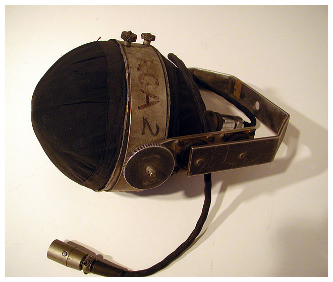
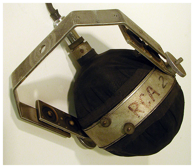
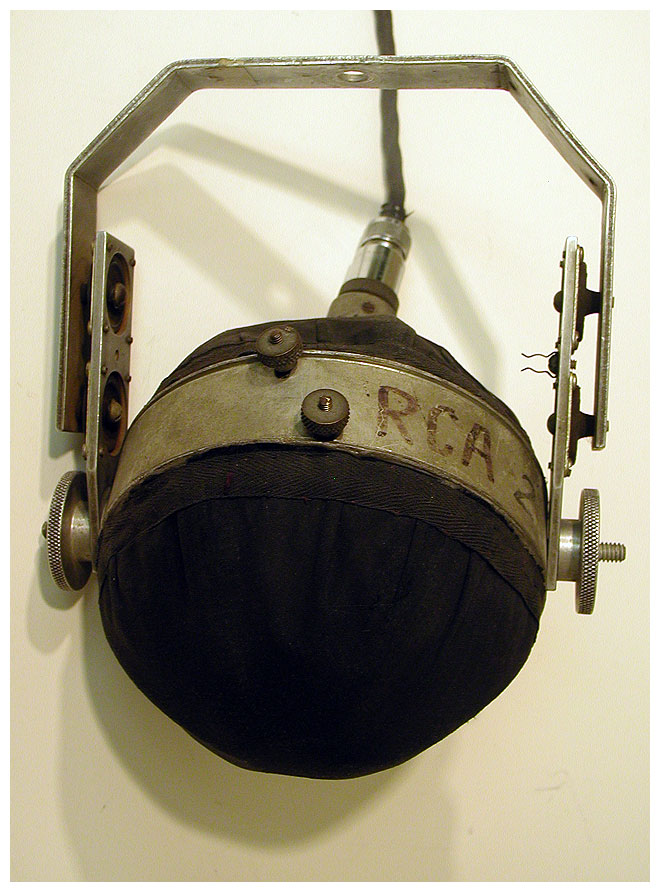
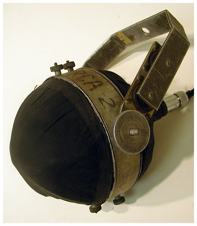
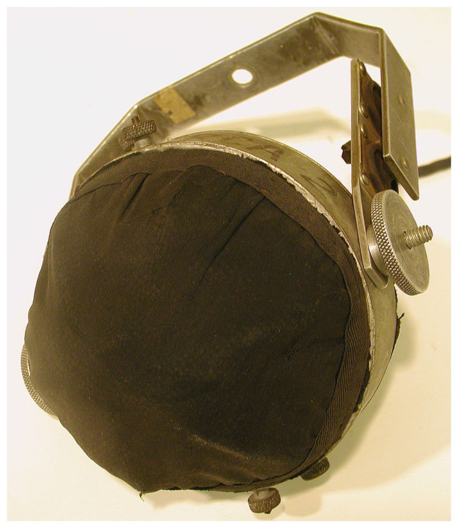
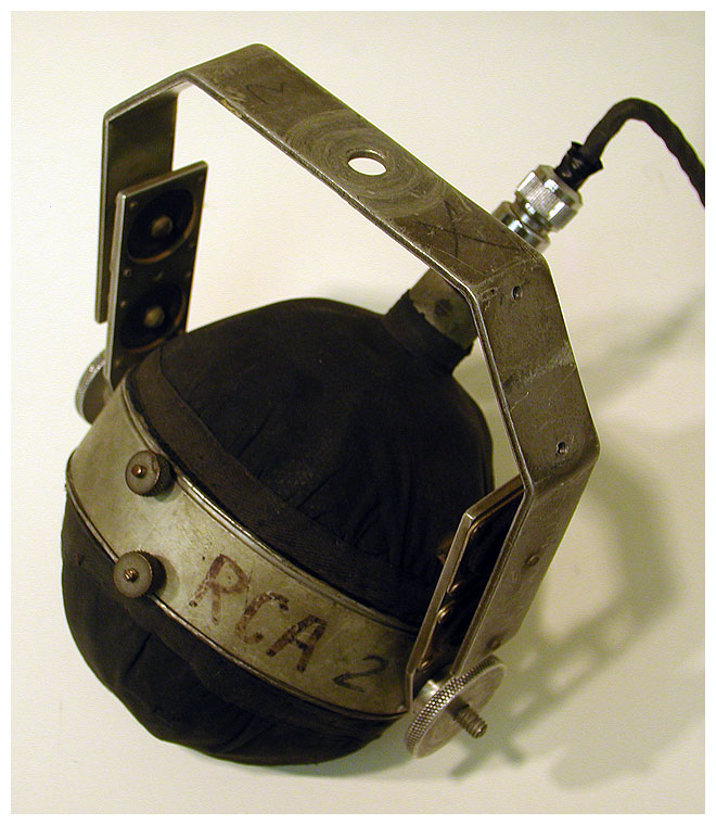
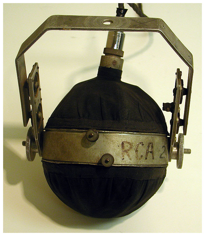
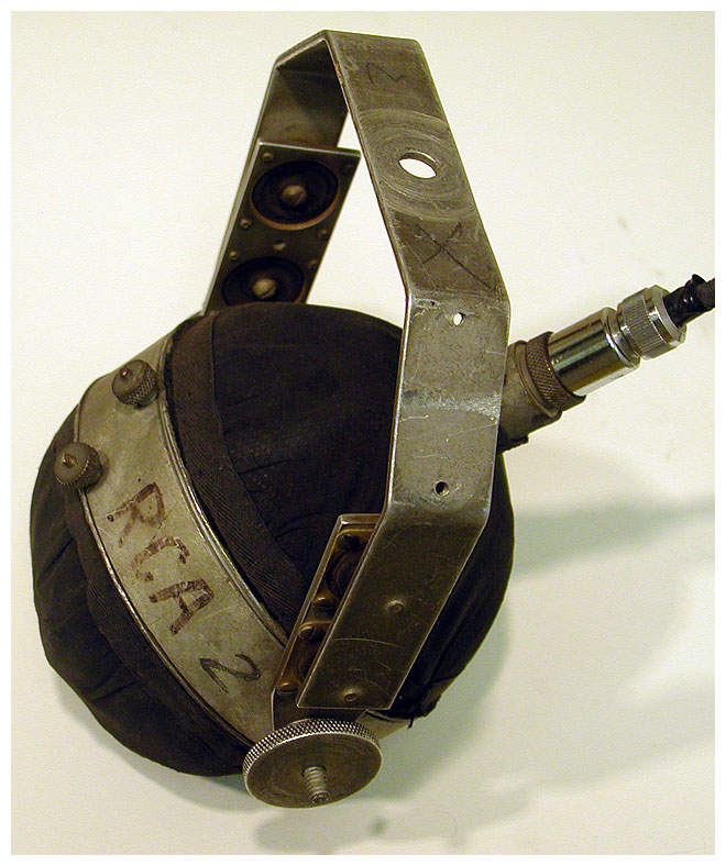
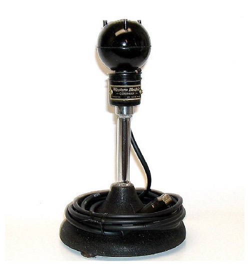
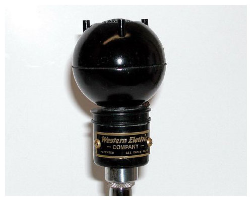
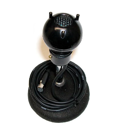
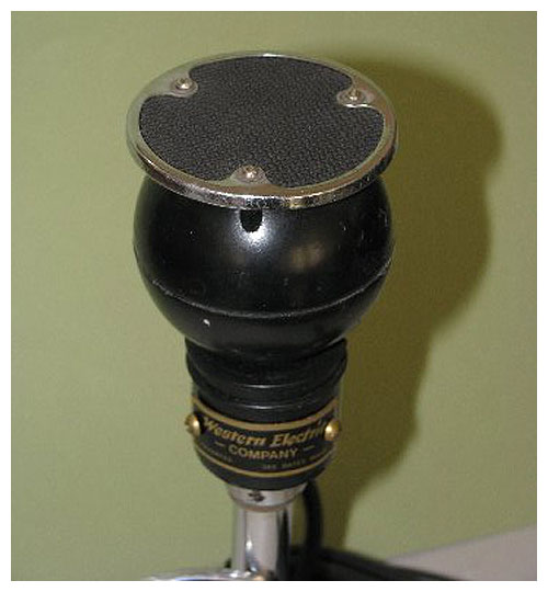
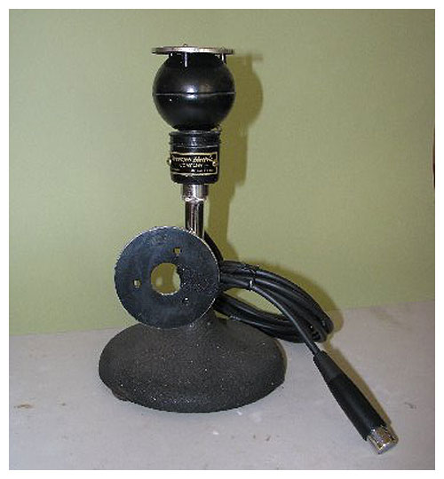
Mr. Gunn has these questions and comments: Recently I received what turns out to be a Western Electric 630A “8 Ball,” but with a larger front disc which makes it unidirectional, and is suspended in a windscreen. The rubber suspension is still in very good shape. Any ideas what it’s worth? I’ve never had one in thirty years of equipment trading. Someone wrote RCA-2 on it but I’m pretty sure it is Western Electric. It was no doubt a boom mic used for film work. It was from the estate of Los Angeles recording engineer Bill Lazerus.
A Non-Directional Microphone
By R. N. MARSHALL Transmission Instruments Engineer BELL TELEPHONE LABORATORIES
Since its introduction in 1931, the Western Electric moving coil microphone has solved many of the difficulties encountered in broadcasting, sound recording, and public address service. While this microphone was a decided advance over apparatus existing at the time of its introduction, extensive field experience during the past four or five years and continued development studies have now made possible the production of a distinctly better instrument. While retaining all the good features of the previous, or 618A, type the new microphone has the added advantages of a more uniform frequency characteristic from 40 to 10,000 cycles, a considerably wider range than the 618A, and is essentially non-directional in its response. At the same time the microphone is smaller and lighter than the old, and thus of increased portability and convenience. It differs radically from previous microphones in appearance, consisting of a two and one-half-inch spherical housing and a two and one-half-inch acoustic screen held a fraction of an inch off the surface. This microphone is known as the 630A.
To build a microphone that will respond uniformly to sound pressures at its face is quite a different thing—and much simpler—than designing it to respond equally to sound coming from any direction. In general a sound field is disturbed by the presence of the microphone, and as a result the pressure at the face of the microphone will not be the same as it was before the microphone was placed in position. This change in pressure caused by the presence of the microphone is largely an effect of diffraction. It is limited to the higher frequencies, varies with the frequency, and is a function of the size and shape of the microphone and the direction from which the sound waves approach the microphone. Because of this, previous microphones have shown a marked directional effect, which not only varied with the angle of sound incidence, but for any particular angle varied greatly with frequency.
This varying in response with direction and frequency results in a distortion of the output. In many cases—such as when used as a pickup for large orchestras or choruses, or in sound picture studios—the sound reaching the microphone directly is only a small part of the total. The major part of the sound reaches the diaphragm only after one or more reflections from the walls of the room. As a result most of the sound arrives at the microphone from directions other than the normal one. If the response in these various directions differs, the output of the microphone will not truly represent the sound at the point of pickup—and this, of course, is distortion. In the new microphone this directional distortion is so slight as to be imperceptible.
Figure 1 — Field response of 618A microphone over the frequency range from 40 to 10,000 cycles for five angles of incidence.
The directional effect for the 618A microphone is shown in Figure 1 for five angles. At 10,000 cycles the difference in response between certain angles is 20 dB, and at 5,000 cycles may be over 15 dB. In the new microphone this variation has been greatly reduced, as shown in Figure 2. At 10,000 cycles the maximum difference in response for any two directions is only about 5 dB, which is imperceptible to the ear. Moreover the new microphone is designed to be mounted so that its diaphragm is horizontal, and thus its response is perfectly uniform for all horizontal angles. The very slight residual directional effect exists only in the vertical plane. When it is used for picking up addresses or other sounds arriving only in the horizontal plane, there is no directional distortion whatever.
Figure 2 — Field response of new 630A moving-coil microphone for the same five angles of incidence and for the same frequencies. Zero dB = 1 volt per bar (open-circuit voltage across output impedance of 20 ohms).
This great improvement has been made possible by extensive study of the causes of the directional effect and the possible means of avoiding it. The directional effect is largely a function of the size of the microphone relative to the wavelength of sound. It might be avoided, therefore, if the microphone could be made small enough, but calculations showed that to make the effect negligible at 10,000 cycles, the instrument would have to be approximately ½ inch in diameter. While a microphone of this size could have been built, its output would be considerably less than for the larger instruments, which is objectionable in a microphone designed for general broadcasting and sound picture use. The size of the new microphone was reduced, therefore, only to the point where a satisfactory output could still be obtained, and the remaining tendency to directional distortion was overcome in the design chiefly by employing a spherical shape and by using the acoustic screen mounted just in front of the diaphragm.
Studies made in these laboratories clearly brought out the effect of the shape of the microphone on the directional response. This is indicated in Figure 3, which shows the computed response at a point at the center of three different shaped objects of equal diameter with variation in frequency and direction of arrival. The abscissas are given as the ratio of the diameter of the object to the wavelength of the sound, but the table at the bottom indicates the corresponding frequencies for the diameters of 1, 2, and 4 inches. It will be noticed that both the cylinder and cube result in a marked directional effect, made more serious by the wavy character of the response, while the variation in response for the sphere is much less and the waviness has practically disappeared.
Figure 3 — Difference of response at the center of the end form of a cylinder, cube, and sphere for sounds coming from different directions and at different frequencies.
With a spherical microphone mounted with the diaphragm horizontal, there would be a tendency for the response to be too high for high-frequency sounds coming down from above, that is directly toward the diaphragm, and too low for similar frequencies coming from angles very much below the horizontal. These effects have been almost completely avoided in the new microphone, and an essentially uniform response obtained from sound coming from all directions, by mounting an acoustic screen in front of the diaphragm. This screen was developed by F. F. Romanow, and is designed to produce a loss in sound passing through it, and to reflect back to the diaphragm sound coming from behind the microphone. It thus compensates for the unequal diffractive effects and makes the instrument non-directional in its response characteristics.
Besides these changes designed primarily to reduce the directional effects, extensive changes were made in the internal construction and arrangement of the microphone to even out the response curve and to extend its range. The general construction is shown in Figure 4. In many of the earlier types of microphones, the cavity in front of the diaphragm introduced an undesirable resonance. In the new microphone this resonance is controlled by the design of the protective grid, which is that part of the outer shell directly in front of the diaphragm. Instead of being the source of undesirable distortion, the grid and cavity have become a valuable aid in improving the response of the instrument at very high frequencies. This grid also incorporates a screen to prevent dust and magnetic particles from collecting on the diaphragm.
Figure 4 — Simplified cross-sectional view of the non-directional microphone.
The inherent loss due to the reduction in size is partially offset by making the diaphragm light in weight and of low stiffness. It is very important that the diaphragm should vibrate as a simple piston throughout the entire range. To secure such action over a wide range of frequencies has proved in the past to be a very difficult problem. This problem has been solved quite satisfactorily in connection with the new microphone. No evidence of vibrating in other modes is shown by the diaphragm below 15,000 cycles.
The size and shape of the housing was selected with particular reference to the requirements that had to be met. The size is such that the housing fits closely over the diaphragm and thus produces little more diffractive effects than would the diaphragm itself, and the spherical form allows the maximum amount of air space behind the diaphragm, which is essential to minimize the impedance to vibration. To prevent resonance within the case, an acoustic-resistance baffle is provided to divide the space into two parts. A tube, with its outlet at the back of the housing, serves the dual purpose of equalizing the inside and atmospheric pressures, and of increasing the response of the instrument at low frequencies.
The acoustic screen that compensates for the directional effects is mounted over the grid in front of the diaphragm, and is thus an additional protection for the diaphragm. This places it in a vulnerable position, however, but it is designed to withstand considerable shock and the acoustic screen itself is a separate unit and easily replaceable. The terminals of the microphone are provided in the form of a plug recessed in the housing behind the microphone unit. This arrangement provides protection for the terminals and serves to conceal the connecting jack.
Thoroughgoing research and development studies have thus not only made it possible to provide a microphone that is smaller, more easily handled, and more attractive in appearance than previous types, but have extended the frequency range and reduced the directional effects to a point where they are imperceptible. Its convenient form and desirable characteristics make the new microphone suitable for practically any type of service.
Reprinted from Bell Laboratories Record, October, 1935
Photographs and voice sample are by Ellis Dawson.
Acoustic Baffle Assembly
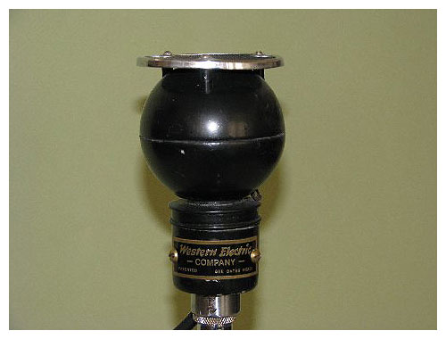
The new Western Electric Acoustic Baffle Assembly enables you to greatly increase—at small cost—the usefulness of your Western Electric 630A Microphone. For this small additional investment you can convert, at will, your 630A into a semi-directional microphone. Here is an opportunity to obtain what, in effect, amounts to two microphones in one.
Field experience with the 630A has proved its exceptional non-directional response, especially where a wide angle of pickup is desired. With the new Acoustic Baffle Assembly—designed by Bell Telephone Laboratories—the 630A, converted into a semi-directional mic, has a response comparable to the Western Electric 618A. Typical response curves of the 630A Microphone (with the Acoustic Baffle Assembly) are shown below and may be compared with those of the 618A Microphone shown above in Figure 1. The studio technique for the 630A with this new equipment is similar to that employed for the 618A.
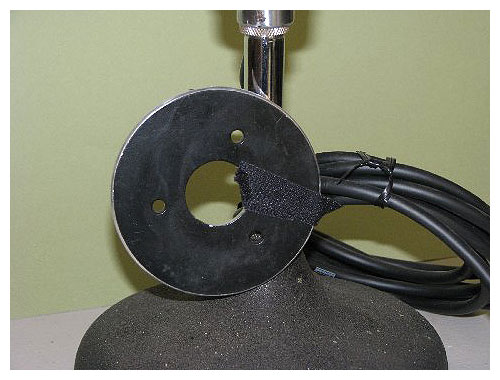
Few Parts Needed—The parts necessary to make the conversion are few in number. They consist of the 7A Transmitter Attachment, the 9A Transmitter Attachment and the 708A Adapter. The 7A Transmitter Attachment is composed of a 3¼-inch baffle, a chromium ring to one side of which two thicknesses of silk screen are attached, and three screws with washers. The 7A Attachment may be used either with or without the chromium ring and screening. Omission of the ring and screening results in the higher frequencies in the range of from 7,000 to 8,000 cycles becoming more predominant, as will be observed from the curves shown in the illustration below.
The 9A Transmitter Attachment is a swivel joint which permits the angle of the microphone to be varied. This allows the microphone to be pointed at the sound source. A special locking arrangement holds the swivel joint securely at the desired angle. The 708A Adapter is used between the 9A Transmitter Attachment and the 442 type jack.
Conversion Is a Simple Procedure—The procedure necessary to make the conversion is basic. All that is required is: first, remove the acoustic screen from the 630A Microphone. Second, place the 7A Transmitter Attachment on the studs and secure it in place with the three screws provided for that purpose. Third, screw the 9A Transmitter Attachment into the top of the microphone mounting, and insert the 708A Adapter between the 9A Transmitter Attachment and microphone jack.