
Frequency coverage is continuous from 1.8 to 30 megahertz.
NVIS reflective function is optimized for sixty meters.
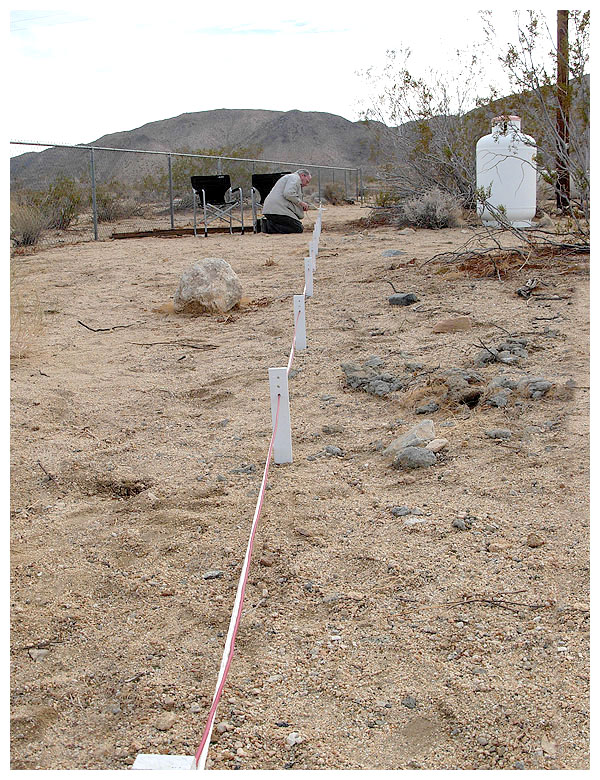
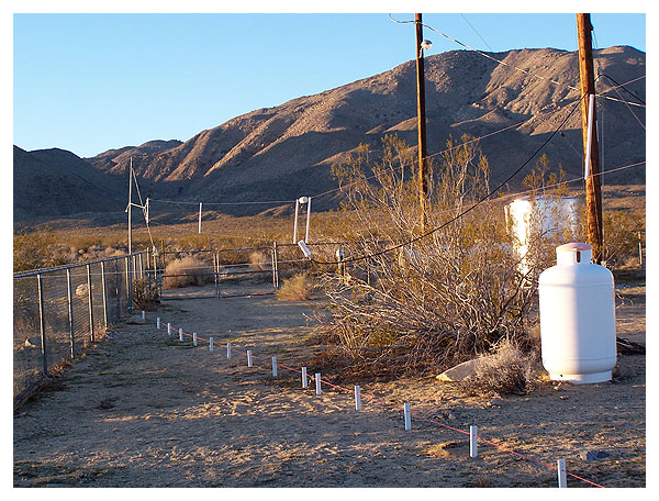
Installing the passive reflector prior to erecting the antenna.
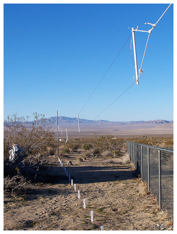
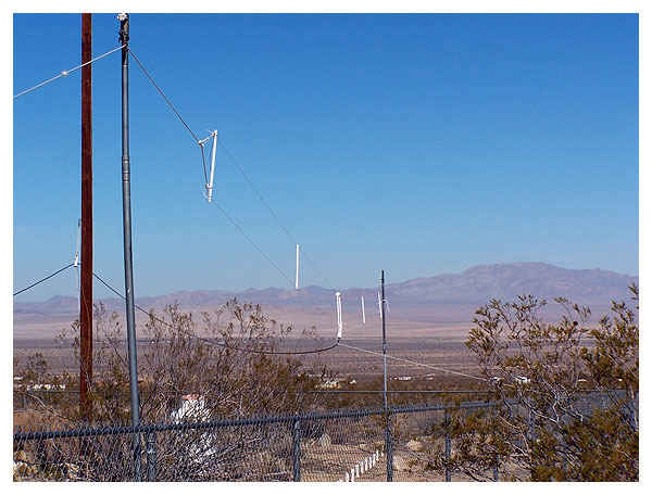
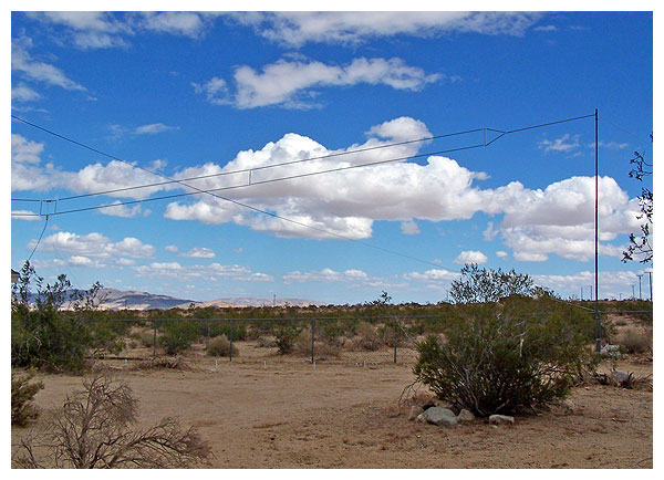
Looking south along the folded dipole antenna at AA6SC/N6TOH.
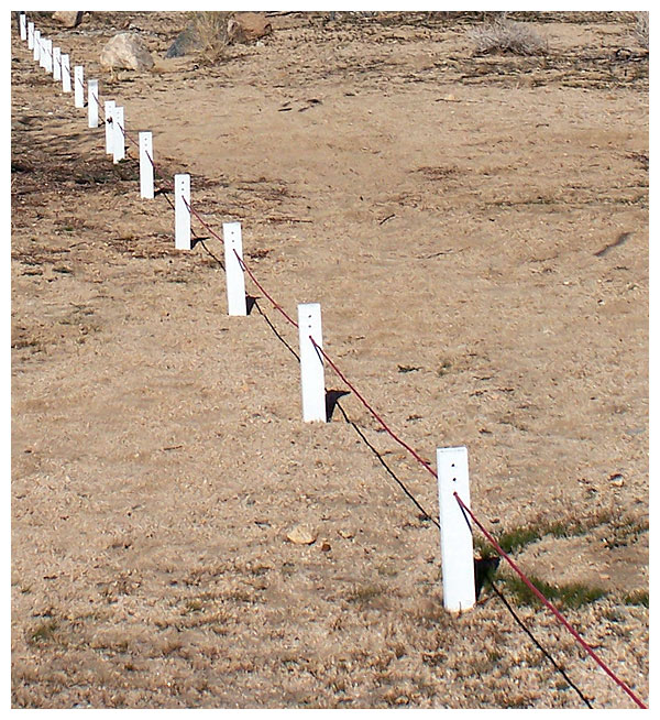
The 5-MHz parasitic reflector runs through wooden stakes driven into the Earth.
This passive element is not grounded, nor is it wired to the dipole above.
The red-insulated reflector wire is joined in the center with a toggle switch.
Opening the switch disrupts its tuned reflective properties.
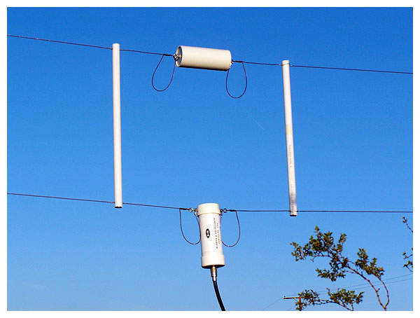
A close-up of the resistive termination and balun, fed with 52-ohm coaxial cable.

An alternate view of the feed point.
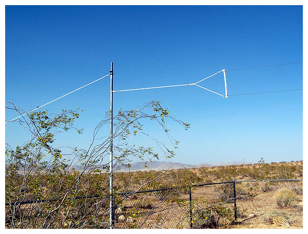
Detail view of the antenna’s northern end.
A close-up of the antenna’s southern end.
The antenna is ninety feet in length; the reflector is ninety-six feet, four inches long
and is constructed of twelve-gauge insulated multi-strand copper wire.
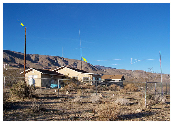
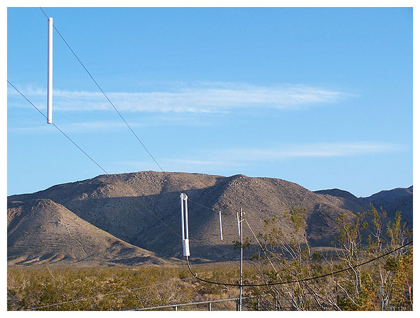
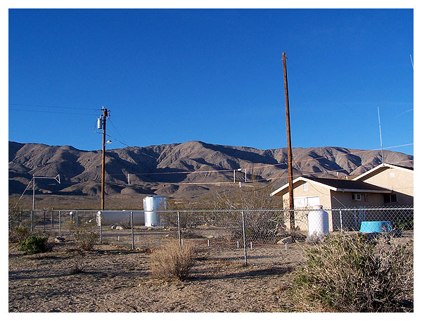
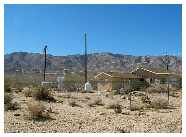
Other antennæ include two- and ten-meter ground planes, and an HF long wire.
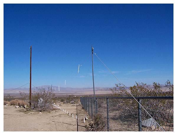
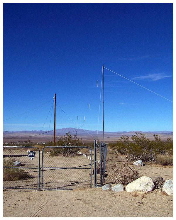
The long wire stretches between two utility poles marked with yellow arrows.
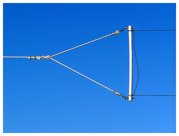
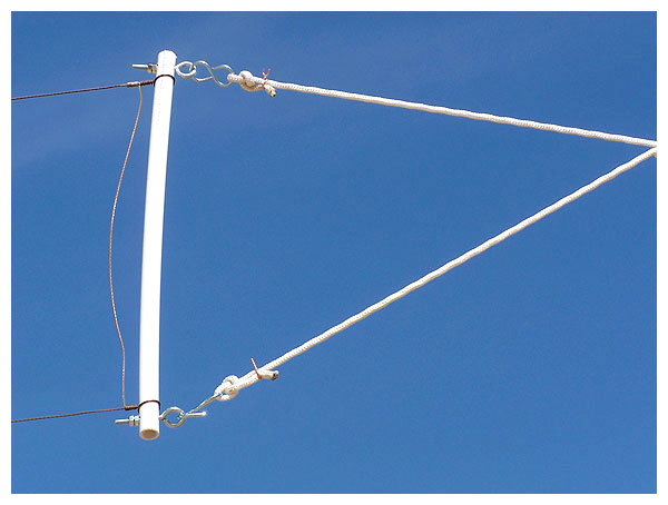
Masts are bolted to fence posts and guyed at their tops to balance the antenna load.
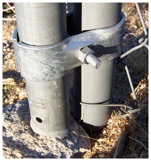
Two clamping techniques and two bolt types were
considered in order to combat desert winds.
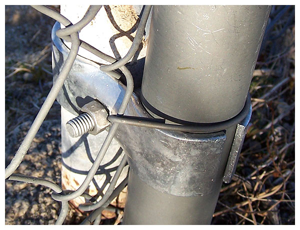
Here we see ordinary galvanized nuts and bolts used in a clamping configuration.
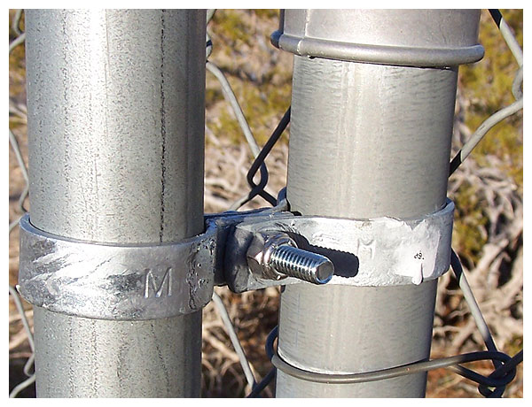
Plated bolts and nylon insert stop nuts hold separate
bands that independently surround each pipe.
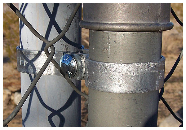
Two years later, both clamping methods remain secure.
Only the fence post bottom ends are buried in concrete.
The NVIS folded dipole and the long wire are at right angles to each other.
The upper lead of the dipole is eleven feet above the reflector.
The objective of an NVIS array is to radiate most of the signal straight up,
where it will reflect off the ionosphere and return to Earth with continuous
coverage out to a 200-mile radius or greater, but without a skip zone.
The illustration above and other pertinent data can be found in NVIS Army Field Manual 2418, Appendix M with Graphics, Near-Vertical Incidence Sky-wave (NVIS) Propagation Concept, by following http://www.athensarc.org/fm2418m.asp courtesy of Mr. Harold Melton, KV5R.
A white nylon line runs from the coaxial cable to the fence
to dampen the antenna’s swinging in the wind.
An overall view. Links to additional information are below.
Disclaimer: I have no financial interest in B & W,
and I paid full retail price for my new antenna.
Thanks for your time spent in looking.
Observations: 1. Rapid fades are lessened when using the nvis antenna compared to signals heard while using the long wire antenna. Sometimes the signal strength from Station A is greater than that from Station B while using the long wire, and switching to the nvis dipole reverses this trend. As the two antennæ are at right angles to each other, with the long wire at more than twice the height above ground as the folded dipole, this comes as no surprise.
2. Atmospheric noise is less noticeable when using the nvis antenna, particularly on forty meters. This may well be due to the fact that the nvis array is at right angles to the Southern California Edison Company’s power line.
3. With an MFJ swr analyzer connected to the nvis coaxial transmission line at the operating position, opening and closing the parasitic reflector’s switch causes slight variations in resistance, reactance, impedance, and swr readings.
4. Switching between the two hf antennæ often shows no appreciable change in received signal strength, while on some occasions it makes a huge difference of up to 6 dB. This too comes as no surprise.
5. It seems fair to say that any horizontal antenna could be configured for nvis operation. These remarks are not meant to suggest that this folded dipole antenna was designed exclusively for nvis applications. Obviously the 5-MHz parasitic reflector and the minimal height of the antenna are what make this installation suitable for nvis use. On the following page you can view a panorama of the entire array by scrolling horizontally.
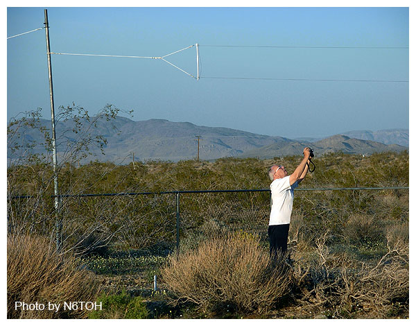
AA6SC attempts to find the best composition for photos on this page.
 OCTOBER 2010 UPDATE: After two and a half years, I determined that the antenna
was not performing as well as I had hoped, so we doubled its height to twenty-three feet.
Improvements of about 6 dB were noted in both transmitting and receiving signal strength.
To continue calling this antenna array an NVIS at its new height is no longer accurate.